The RF BJT Amplifier with standard BJT model for DC bias analysis. Designing a Distributed RF BJT Amplifier Examining the High Frequency BJT Model.

4 Stage Distributed Amplifier Optimised Circuit Download Scientific Diagram
To start with generate the ombre impact by dabbing the colors within the nail with a makeup sponge apart from the accent nail.

. Free space path loss 20log 10d 20log 10f -14755 dB Friis formula expressed in dB 1m at 6GHz. Class D Amplifier Design Basics II 02192009 Rev 10. DAS works by receiving power from a radio frequency RF source and distributing it over a system.
Distributed Antenna System DAS Tutorial Design. Design and Simulation of Synthesizers PDF - 15MB 19 Basics of Wireless Communication 20 Performance Measures of Wireless Communication. Index Termsdistributed amplifier broadband amplifier microwave circuits I.
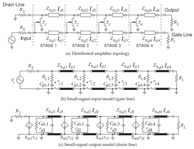
Distributed Ampli er v s v o Zd Z g M1 M2 M3 M4 dZ d gZ g g d Z Z g The goal is to convert the lumped ampli er into a distributed structure. Input degernation with distributed amplifier at the upper 3 - dB design frequency of the amplifier Suppose we apply degeneration to make G 11new G 22new max 11 22 2 2111 22 221 2 0 221 2 2 max 21 max 11 0 max 22 0 max in 11 0 out 22 0 11 0 4 4 4 Circuit power gain 1 Maximum sections. On-chip spiral inductors were utilized in on-chip bias circuitry.
The design is internally stable as well. Faculties and often novel design capabilities for a given IC process. The principle has been applied in many other devices including lasers traveling wave tubes and most relevant to us.
Amplifier Chapter 4 Reducing Distortion Dead-time LPF Designs Chapter 5 Reducing Noise Isolation Technique PCB Design APPENDIX Simulation of a Simple Class. Various embodiments described herein comprises an optoelectronic device comprising a waveguide structure including a plurality of optical modulator elements each having an optical property that is adjustable upon application of an electrical signal so as to modulate light guided in the waveguide structure. A distributed amp is a clever way to provide enormous bandwidths as much as 100 GHz.
The idea is to take a xed g m transistor width W and split it into parallel ngers that are embedded into a transmission line at the gate and drain. G G G Y. One transmission line connects the inputs or gates of the devices in a FET based amplifier and is then terminated with a resistor.
2 Contents Chapter 1 Getting Familiar with Class D Audio Amplifier Chapter 2 Latest Class D Audio Amplifier Technology Trend. Thats correct Ombre and Glitter in a single manicure. The design of the distributed amplifiers was first formulated by William S.
In that year Percival proposed a design by which the transconductances of individual vacuum tubes could be added linearly without lumping their element capacitances at the input and output thus arriving at a circuit that achieved a gain-bandwidth product greater than that of an individual tube. The theory behind the distributed amplifier is that a number of FETs at least two but more typically four five or six are fed by a periodic structure at the input that resembles a. Design issues in DA gain stages.
68dB High path loss enables reuse of the spectrum Use of directional antenna arrays. The goal is to design a distributed BJT amplifier for maximum gain at f 4GHz. In Virdees book they use a chip FET and use wire bound as inductors.
Some distributed amplifiers can operate down to DC as well so they are used as opto-electronic amps. The DA stability is compromised when using multi-stage amplifiers as gain stage. INTRODUCTION he principal of distributed amplification was originally applied to vacuum tubes structures1.
Both transmission lines need to be properly terminated to see. Design of a broad-band distributed amplifier and design of cmos passive and active filters dalpatadu k. Building the BJT Amplifier and Its DC Bias Circuit.
The optoelectronic device also comprises a plurality of amplifiers. Basics of 60GHz LNA and PA Design in CMOS 10 of 82 Consequences of short wavelength High path loss For distance d. 1 2 2 2 2 Line losses per section.
Obtaining 3D decorations created from plastic and glue them with your nail or you can find your own acrylic and paint your very own nails. The other transmission line connects the outputs or the drains in a FET based amplifier and provides the output of the amplifier. Let me try to find it.
Radike samantha beng hons nus national university of singapore 2011. 48 dB at 60GHz. Distributed amplifier design tutorial provides a comprehensive and comprehensive pathway for students to see progress after the end of each module.
Noise contribution of G m stage should be low. Enhancement of Broadband Amplifiers Narrowband Amplifiers 7 Noise Modeling in Amplifiers 8 Noise Figure Impact of Amplifier Nonlinearities 9 Low Noise Amplifiers 10 Mixers 11 Voltage Controlled Oscillators. In Moez 2008 a further design method based on the modified distributed amplification method was proposed.
Why select Ombre or Glitter if you may have the most effective of both of those worlds. The distributed a mplification method can provide a. With a team of extremely dedicated and quality lecturers distributed amplifier design tutorial will not only be a place to share knowledge but also to help students get inspired to explore and discover many creative ideas from.
RF Tutorial Lesson 9. I have done it for few years. BW of DA is limited by BW of G m stages.
DAS stands for Distributed Antenna System which is a system that allows for the use of cell phones and other wireless devices in areas that do not have direct access to a cell tower or power source. Distributed amplifier design example As a starter you may make your personal Nail Artwork Impact applying two strategies. Distributed amplifier design tutorial.
G m variations with freq. High Efficiency Power Amplifier Design 247 Overdriven Class B 247 Class F Circuit Design 250 Inverse Class F 264 Class E with Shunt Capacitance 271 Class E with Parallel Circuit 279 Class E with Transmission Lines 286 Broadband Class E Circuit Design 299 Practical High Efficiency RF and Microwave Power Amplifiers 305 Chapter 8. Distributed Amplifier Design Example.
In this tutorial after a brief description of the typical structure of a millimeter-wave receiver the design simulation layouts and measured results of Microwave frequency Distributed Oscillators and broadband Distributed Amplifier will be presented. Distributed amplifier tutorial I have tried to design some distributed amplifier using the book by Virdee. Affect the DA gain flatness.
From the S-parameter data of the RF BJT at 4GHz you find that Δ 0488 -162 K 1195 Γ S 0872 123 Γ L 0876 61 G Tmax 167dB. Building Testing a Distributed RF BJT Amplifier The following is a list of parts needed for this part of the tutorial lesson. Consequently the focus of this thesis is upon the application of distributed integrated circuit methodologies towards the realization of a distributed broadband amplifier in a commercial CMOS process technology.
The distributed amplifier functions by creating a pair of transmission lines. High G m value is desired to enhance DA gain. Some state that it demands a large amount of expertise on painting your own.
I do have design examples using ADS. High frequency transistors are typically characterized by their S- parameters. I dont know this approach will be good up to 10 GHz or not.

Shows Schematic Diagram Of Two Way Combined Amplifier Each Way Download Scientific Diagram
Microwaves101 Distributed Amplifiers
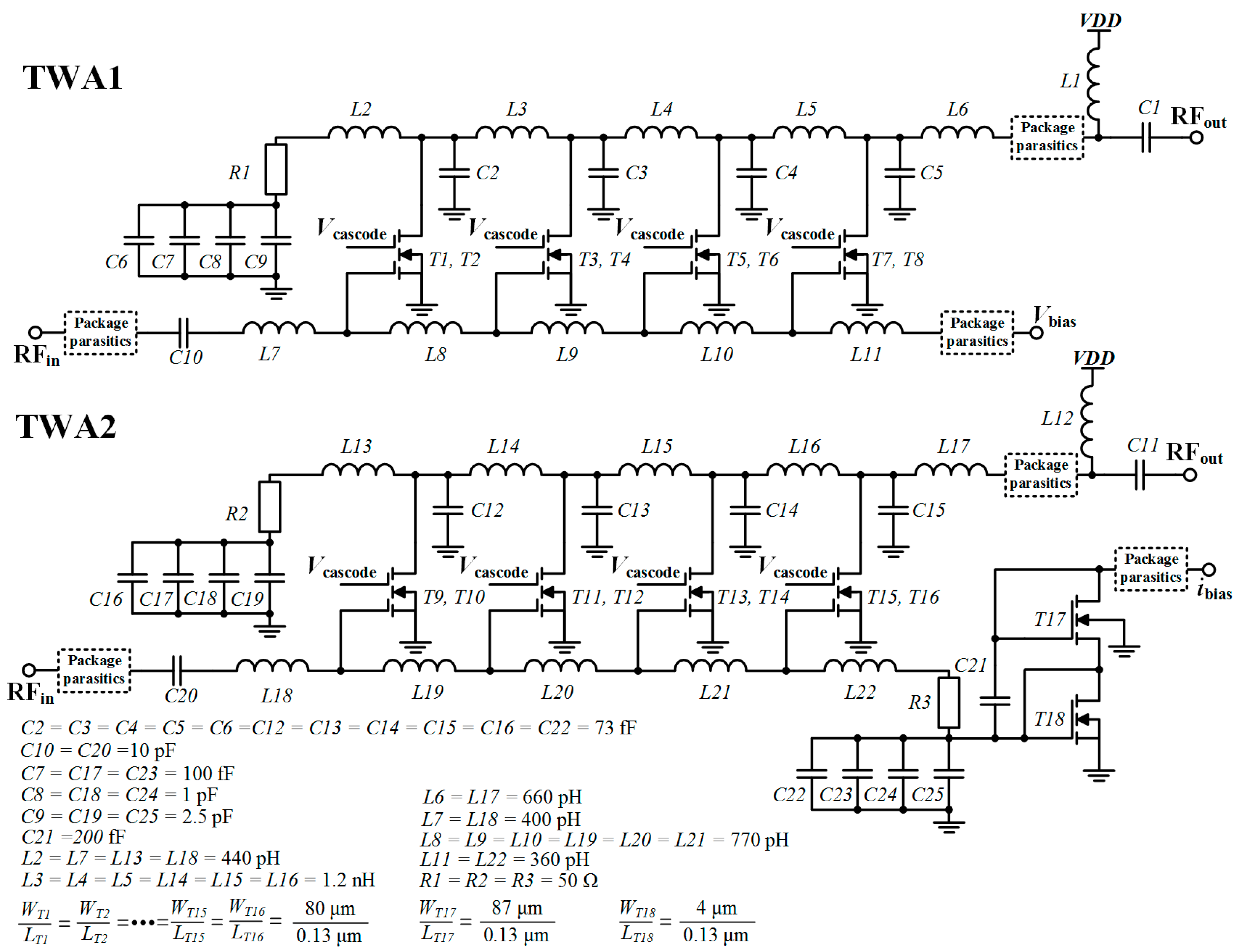
Electronics Free Full Text 0 13 Mm Cmos Traveling Wave Power Amplifier With On And Off Chip Gate Line Termination Html

Case Study Analysis Of A Distributed Amplifier By Michael Steer Youtube

Rf Design 17 Practical Power Amplifier Design Part 2 Youtube
1 41us 21 Off Official Tpa3110 Xh A232 30w 30w 2 0 Channel Digital Stereo Audio Power Amplifier Board Dc 8 26v 3a C6 001 Integrated Circuits Aliexpress Power Amplifiers Amplifier Audio
3 2 Distributed Amplifiers Engineering Libretexts

Designed For Wall And Ceiling Paneling The System Responds Dynamically To The Soundscape Of A Space Origami Architecture Diagram Architecture Acoustic Panels
0 comments
Post a Comment